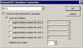
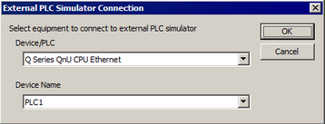
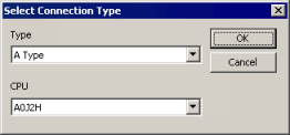
[External PLC Simulator Connection] dialog box displays when the following operating environment is set up.
Required software is installed
Device/PLC used in the GP-Pro EX project is supported by the external PLC simulator
![]() 33.5 Checking Display Unit operation and PLC interaction on the Computer
33.5 Checking Display Unit operation and PLC interaction on the Computer

Connects with external PLC simulators
Sets a connection between GP-Pro EX and the external PLC simulator.
Select to check display unit operations with the device/PLC.
![]()
When you want to check screen operations only, clear the [Connect with external PLC simulator] check box.![]() 33.2 Checking Display Unit operations on the Computer
33.2 Checking Display Unit operations on the Computer
Select the external PLC simulator to connect.
Select the device/PLC manufacturer's simulation software.
When using MX Component Ver4

PLC*
The device name defined in the [System Settings]-[Device/PLC]-[Device Name] field is displayed in a list.
![]() 7.9.1 System Settings [Device/PLC] Settings Guide
7.9.1 System Settings [Device/PLC] Settings Guide
From the pull-down menu select the device/PLC to connect with the external PLC simulator.
For each device selected, define its associated settings in this dialog box. (The defined settings are preserved even if you change the device/PLC in [PLC*].)
Connects with external PLC simulators
Connects the device/PLC selected in [PLC*] to external simulation.
Only devices/PLCs with their [Connects with external PLC simulators] check boxes selected are simulated.
Use unit number
Select this check box if you want to run simulation in a multiple CPU system.
This setting is available when the device/PLC selected in the [PLC*] list supports multiple CPU systems.
Logical station number
For the unit number, define the logical station number from 0 to 1023 as set up in MX Component.
This setting is available when the [Use unit number] check box is not selected.
Logical station number for Unit*
For each unit number, define the logical station number from 0 to 1023 as set up in MX Component.
This setting is available when the [Use unit number] check box is selected.
Default unit number
When the unit number for the device/PLC selected in the [PLC*] list is set to the default (in the [Address Input] dialog box the unit number is 0), define the CPU unit number that is actually accessed from 1 to 4.
This setting is available when the [Use unit number] check box is selected.
![]()
For settings in the [Address Input] dialog box, please refer to the "GP-Pro EX Device/PLC Connection Manual".
When using MX Component Ver3


External PLC Simulator Connection
Device/PLC
Define the name of the driver for simulation.
The device name defined in [System Settings]-[Device/PLC] is displayed in a list.
Device Name
Define the name of the device/PLC for simulation.
The device name defined in the [System Settings]-[Device/PLC]-[Device Name] field is displayed in a list.
Select Connection Type
Type
Select the CPU type for the external PLC simulator.
CPU
Select the CPU model for the external PLC simulator.