If you want to monitor/operate alarms using the EZ Illuminated Switch, do the following:
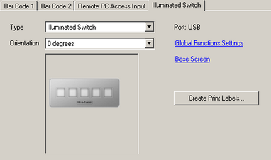
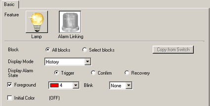
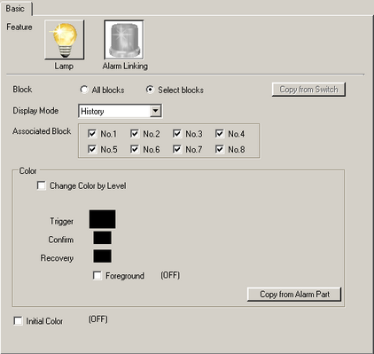
The EZ Illuminated Switch is set up in the [System Settings] node's [Input Equipment].Setting the EZ Illuminated Switch
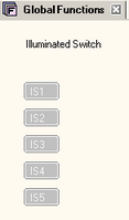
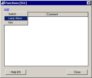
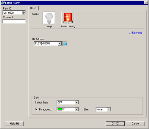
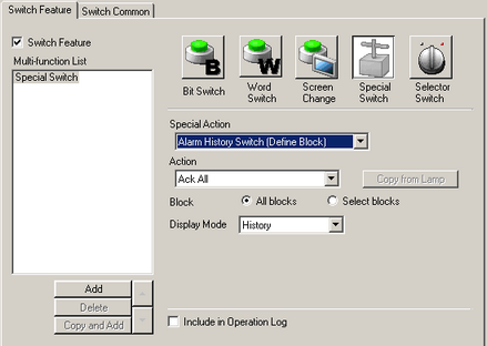
Assign a part to a switch on the EZ Illuminated Switch.Assigning Parts
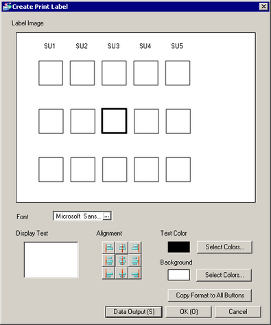
Create labels for the EZ Illuminated Switch.Create Print Label
This section explains the procedure of monitoring the alarm trigger set on block 1 for the whole project. Set up switches so that Switch 1 turns on in red when an alarm is triggered, and so the alarm is cleared by pressing Switch 5.
Please refer to the Settings Guide for details.16.6.2 System Settings [Input Equipment] Settings Guide - Illuminated Switch
16.6.2.1 Lamp Alarm Settings Guide
For information on the models that support EZ Illuminated Switches, see the following.1.5 Supported Features
EZ Illuminated Switch Settings
From the [Project] menu, select [System Settings] and [Input Equipment], then click the [Illuminated Switch] tab.
From the [Type] drop-down list, select [Illuminated Switch].
From the [Orientation], select [0 degrees].
In the [Input Equipment]'s [Illuminated Switch] tab, click [Global Functions Settings].
If you want to set up a switch that is used only in one screen, click [Base Screen] and set function keys.
Double-click [IS1] to open [Functions].
The following screen appears. Click [Add].
Select [Lamp Alarm] and add parts ID.
Double click the added parts ID to open the Lamp Alarm setting screen.
From [Feature], select [Alarm Linking].
In [Block], select [Select blocks].
Select [No.1] under the [Associated Block]. Clear the check boxes for other blocks.
Select a [Display Mode]. In this example, select [History].
Select [Display Color] and set the color for Trigger to [Red 4]. From [Blink], select [None].
Click [OK] to complete lamp alarm settings.
[Close] exits the function settings dialog box.
Repeat the steps above to set up a switch to clear the alarm on Switch 5. Double-click [IS1] to open [Functions].
Click [Add] and select [Switch].
Double click the parts ID you have added.
Select [Special Switch] in the [Switch Feature] tab.
From [Special Action], select [Alarm History Switch (Block)].
In [Action], select [Clear All].
Select [Select blocks] under [Block], and select [Block 1]. Clear the check boxes for other blocks.
Click [OK] to complete the settings.
To print out labels, set up the printer as follows and then print.
Paper Size: A6
Orientation: Landscape
Margins: None
Creates print label. You can print the labels on a clear film, which you can insert into the EZ Illuminated Switch.
In the [Input Equipment]'s [Illuminated Switch] tab, click [Create Print Label].
Select a font in [Select Font].
The selected font is used for all switches.
In [Label Image], choose a switch for which you want to enter text, then enter the text in [Display Text].
Select [Alignment], [Text Color] and [Background].
The selected background color is used for all switches.
Click [Data Output].
In the dialog box that appears, select a file format from the [Save as type]. You can select [Bit Map File (*.bmp)] or [JPEG File (*.jpg)].
From [Resolution], select the resolution for the output file, and save in a desired location.