The LT4000 Series has the following special features.
Logic Feature
I/O
PLC Communication
Refer to the following for information about changing the model from LT3000 Series to LT4000 Series.
 5.6.1 Restrictions on Changing Models
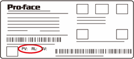
If the version (PV) of the LT4200/4300 series display unit is 02 or later, it can also be used as LT-Rear Module series models.
Check the product label for the display unit version (PV).

When the display unit's product label is "PV:02, PL:03, SV:2.0" or later, use GP-Pro EX Ver.3.5 or later. If you transfer a Ver.3.12 project file, the system variable #L_BatteryErr turns ON and an error message related to clock data will appear.
When using the LT4000 Series, if you set the [Sampling Cycle] to 100ms and sample a large amount of data, the sampling cycle will become longer than 100ms. In order to prevent sampling delays, adjust the number of data using the following word counts as a guide.
When the word address bit length is 16 bits: (number of groups * number of addresses) is 8100 words or less
When the word address bit length is 32 bits: (number of groups * number of addresses) is 4050 words or less
However, there may be a sampling cycle delay regardless of the sampling word count when the load of the logic program etc., being processed is very large.
Make sure that the display module is mounted when you transfer project files or while performing maintenance. It may not be possible to determine whether the setup has been completed properly.
In the System Settings [Display Unit] - [Remote Viewer], place a checkmark in [Pro-face Remote HMI] - [Enable]. If an error occurs, you can check them with the Pro-face Remote HMI.
When using the feature that stores the status in the internal device or the device/PLC address, design the so that the the external device can detect any display unit errors, as needed, by monitoring address values or using I/O.
If you want to use RS-485 to connect to the device/PLC, in the [Communication Settings] select [RS-422/485 (2wire)].
Even if the serial port on the device/PLC uses 4-wire signals, when your device supports 2-wire communication, there are drivers that support that format by short circuiting the send+ and receive+, and send- and receive- signals. See the cable diagrams listed in the "GP-Pro EX Device Connection Manual".
 5.6.1 Restrictions on Changing Models