As simulation does not communicate with the device/PLC, simulation will not retrieve communication-related information.
As a result, the communication scan time is displayed as 0. Plus, the simulation processing speed is different from the actual display unit.
Some functions may operate in the simulation even if they are configured beyond the upper limit number of parts or addresses. Check the upper limit number in the chapter for each part, since it may differ depending on the model.
You can run Simulation on one project at a time.
If the project does not pass the error check (from the [Project (F)] menu point to [Utility (T)] and select [Error Check (E)]), it will not run in Simulation.
When you start simulation, you may see a message generated by your Windows operating system's firewall indicating the application has been blocked. In that case, select [Release Block] and continue with the Simulation operation.
While running simulation, if you use the Windows [Switch User] command to login as a different user then start a new simulation, this is considered multiple starts and simulation will not work properly. Before running [Switch User], exit simulation.
When the GP-Pro EX installation path is longer than 200 single-byte characters, and simulation is started, an error message appears indicating simulation will not activate because the maximum number of characters has been exceeded. Simulation will not run normally in this state. Reinstall the GP-Pro EX to an installation destination with path of less than 200 letters in English single-byte characters.
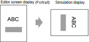
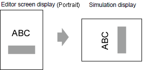
When the display orientation is [Portrait], simulation runs as shown below.
For display units other than the GP-4100 series, rotate 90 degrees

For GP-4100 series, rotate 270 degrees

The virtual device/PLC backup file cannot be read when a simulation of a different project file is running, or when the device/PLC configuration has changed in the same project file. The simulation is activated without the previously stored data.
Some unsupported functions in the model may operate in the simulation because the simulation does not identify the display model. For example, a project file with sound settings could be edited for a model with sound output functions (such as AGP-3550T), and then the model could be changed to one that does not support these sound settings (such as AGP-3500T). When the project is simulated, the sound output function operates. However, the sound output function does not run when this project is transferred to the display unit. For functions supported by each model, see the following.
 1.5 Supported Features
If [System Area Start Address] in the [System Area] tab is not set in the System Settings [Display Unit], project files cannot display the System Area data.
In Simulation, you cannot set up clocks or calendars that use the System Area or system variables. Also in [Common Settings] menu, you cannot select [Clock Update Settings].
When writing data to PLC devices with D-Script, the writing results are not reflected immediately. It takes some time to communicate with display units, but the writing results are immediately reflected in the simulation. If you create D-Script taking into account the time lag to write data to PLC devices, simulation results may differ from the actual operation on the display units.
During Simulation, if you use the [Display] menu's [Option Settings] command to change the language settings, an error message prevents the operation. To change the language, you need to exit Simulation.
You cannot exit GP-Pro EX while executing a simulation. Exit the simulation first.
Files in backup memory (SRAM) are deleted after simulation ends.
The operation log does not record simulation as an operation.
The display unit's filing system is different than a computer. Therefore, the order in which the display unit reads and displays files that are saved in an external storage can be different.
Multiple tags that are assigned to one address in a simulation are executed as individual tags.
Thus, even if you change a value in one of the tags, the other tags do not change.
The following lists features unsupported in Simulation.
System Menu
[Offline], [CF Start] (or [SD Start]), [USB Start], [IP Address], [RGB Settings], [Address Monitor], [Logic Monitor], [Device Monitor], [Ladder Monitor]
Offline mode
Cannot change to offline mode.
Print Feature
Printing alarm banner, alarm history, or sampling data, printing associated with CSV display parts, printing commands in scripts, or printing screen images does not work.
Bar Code Reader
Cannot read in data from a bar code reader.
AUX Output
Cannot output to AUX port.
Playing Movies
The Movie Player cannot display.
When [Select Movie] is selected in the [Action Mode] in the [File Manager] part, the File Manager will not display.
In the System Settings from [Video/Movie Settings], [Save to CF/USB] (or [Save to SD/USB]), [Save to FTP], and [Event Recorder] features do not work.
Image Unit Features
Image Unit Display cannot display.
Image Sensor Displays will not show a picture.
SRAM Backup
All data stored in backup memory (SRAM), such as alarm history, sampling data, recipes (filing), internal device backup, and operation log, is deleted when exiting simulation.
Brightness Settings, Contrast Settings
The brightness and contrast adjustment bar does not appear.
Reverse Display
Even when [Reverse Display] is set on a Monochrome model, the simulation display is not reversed.
Standby Mode
The Standby Mode function does not work.
Retentive Variables
In the [Edit Symbol Variables] dialog box, even though the symbol is set to [Retentive], the data is erased when exiting simulation.
Detect Backlight Burnout
Detecting if the backlight is burned out does not work.
Remote PC Access
The Remote PC Access Window Display does not display.
Change Backlight
The change backlight function does not work using the Backlight Color Settings, 3 color settings, or #H_BackLightColor system variable.
Monitor
Address Monitor, Logic Monitor, Device Monitor, and Ladder Monitor features do not work.
Cross-hairs Cursor
The cross-hairs cursor feature does not work.
WinGP
Device access APIs and handling APIs do not work, and error messages do not save.
The switch features mapped to the function keys on the keypad do not work. After performing the simulation on the IPC, the IPC function keys will not work, either.
Special Switch
Operation Lock, Transfer Device/PLC Data
Logic Feature
Logic, Scan Time, #L_Clock100ms, #L_Clock1sec, #L_Clock1min, Timer Instruction, PID Instruction, and Constant Number System may differ from the actual actions.
Watch Dog Timer, Logic Monitor, and Address Monitor features do not work.
The calculation system of Ladder Instructions may differ from the Display. (Instructions dealing with real numbers, SCL Instructions, AVG Instructions, etc.)
Online Monitor
Online monitor does not work.
Transfer
Transfer is not available.
Function Key Features of Hand-held GP
Operation switches for hand-held GPs can function only as normal function keys.
Multiple function keys will not work when pressed at the same time.
Start Screen
When starting simulation, the initial screen displays instead of the start screen.
Screen Capture / Video snapshot
When captured data save location is [FTP Server], the capture feature will not run.
When using any other save location, captured data is saved to the same location as the [Simulation] menu's [Utility], [Save Screen] function.
Even when you select [USB Storage] as the save location, be careful as it saves to the CF card (or SD card).
 33.6.1 GP-Pro EX Simulation Setting Guide
FTP Function
Copy file to FTP (Special Data Display's [File Manager]) and other features that require FTP do not run.
Checking tag consistency
If project files have tags imported from the device/PLC, checking tag consistency does not work.
2-point touch
On the following display units, even if you set [2-point Touch], simulation works the same way as when you set [1-point Touch] and [Slide Action] = [None].
Display units with PCAP technology
Display units with matrix touch panel technology


![]() 1.5 Supported Features
1.5 Supported Features