You can indirectly specify the address for numeric display. There are two methods for indirect specification.
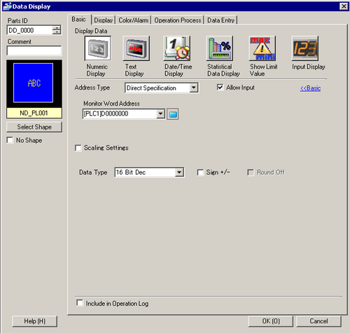
Address Type
You can define the display address (Monitor Word Address) in the following ways: [Direct Specification], [Address], or [Device Type Address].
![]()
If the data type of the address set in the [Monitor Word Address] is BYTE, SINT, or USINT, you can select only [Direct Specification] for the [Address Type].
If the data type of the address set in the [Monitor Word Address] is other than BYTE, SINT, USINT, DATE_AND_TIME, you can select [Direct Specification] or [Address] for the [Address Type].
Allow Input
You can specify to accept input from a keypad, bar code reader, or a two-dimensional bar code reader. When you select this check box, the [Data Entry] tab is displayed.
![]() 14.11.1.3 Numeric Display - Data Entry/Basic
14.11.1.3 Numeric Display - Data Entry/Basic
![]()
This cannot be set if the [Display Format] option is set on the [Display] tab's [Extended] screen.
![]() 14.11.1.6 Numeric Display - Display/Extended
14.11.1.6 Numeric Display - Display/Extended
Monitor Word Address
You can have a real-time numeric display of data stored in the word address specified here. To indirectly specify the Monitor Word Address, in the [Address Type] list select [Address] or [Device Type Address].
![]()
You cannot specify an address with the DATE_AND_TIME data type for the [Monitor Word Address].
Address
Indirectly designates to the device specified in [Base Address].
Base Address/Offset Value Specification Address

The [Base Address] becomes the standard indirectly designated address.
In [Offset Value Specification Address], set the address that stores the offset value from the [Base Address].
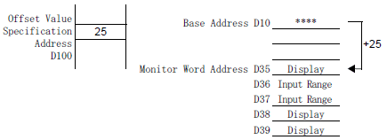
For example, when you indirectly specify [Monitor Word Address] D35
[Base Address] = D10
[Offset Value Specification Address] = D100
The data in [Offset Value Specification Address] is handled as the offset value from the [Base Address].
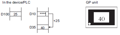
The [Base Address] (D10) is added to the [Offset Value Specification Address] (D100)'s data, which is "25", and the resulting address D35's data "40" displays.
![]()
If the [Base Address] + [Offset Value] operation results in overflowing digits (more than 16 bit), the correct Monitor Word Address cannot be requested. In this case the Monitor Word Address will be undefined.
If you have specified [Address] for the [Address Type], a structure element for the [Base Address], and a value that exceeds the end value of array for the [Offset Value], the correct Monitor Word Address cannot be requested. In this case the Monitor Word Address will be undefined.
Bin/BCD
Choose the type of data stored in the [Offset Value Specification Address] from [Bin] or [BCD].
Device Type Address
Indirectly designates both the device and address.
Device/PLC
When [Address Type] is [Device Type Address], select which device/PLC's address to indirectly designate.
Device Specification Start Address
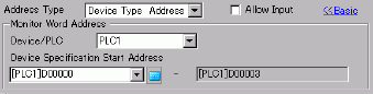
Input the start address of the word address to specify the Display Address in [Device Specification Start Address]. Store the Address Mode in [Device Specification Start Address]. Address Mode is the mode to determine if the Device Address is for Internal or External (PLC) Device. Store the Device Code and the Address Code in the three Words following [Device Specification Start Address]. The word address specified with the Device Code and the Address Code will be displayed.
For example, when you indirectly specify [Monitor Word Address] CN35
[Device Specification Start Address] = D100
[Address Mode] = External (PLC) Device
[Device Code] = CN:0061
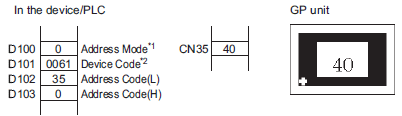
*1 Address Mode0: External (PLC) Device 1: Internal Device stores 0 in the above example.
*2 Refer to "GP-Pro EX Device Connection Manual" for information about device codes. To specify the internal device in the Address Mode, use device code 0x0000 for the LS device, and device code 0x0001 for the USR device.
The address designated by D100, D101, D102, and D103 is CN35. Its data, "40" displays.
![]()
If the indirectly-designated address is out of range or does not exist, a communication error will occur. An error can affect the screen update. When an error occurs, check the indirectly-designated data and write the correct value to the device/PLC address to restore the screen update.
Displaying Numeric Data as Relative Values (Indirect Specification)
On the [Basic] tab's Extended screen, when you set the [Address Type] to [Address] or [Device Type Address], and set [Specify Source Range] and [Display Specification] to [Address], you can allocate the addresses that store the maximum/minimum values for the Source Range/Display Range to the addresses following the Monitor Word Address.
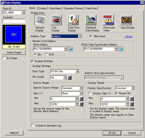
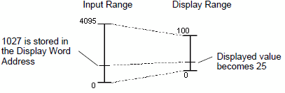
Scaling Settings
When Scaling Setting is performed, the [Monitor Word Address] data is automatically converted according to the Source Range and the Display Range. The results are displayed in numeric values. (Display relative values)
For example,
Data Type
Select the type of data to be displayed.
|
Bit Length |
Data Type |
|---|---|
|
16 bit |
Dec, Hex, Oct, Bin, BCD |
|
32 bit |
Dec, Hex, Bin, BCD, Float |
Bit Length
Set the valid bit length of the address to be displayed.
Selectable only when [Data Type] is specified as [16 Bits].
[16 bits]: 1 to 16
Indirect Area Specification
Displayed when [Address] or [Device Type & Address] is selected at [Address Type], and when [Address] is selected at both [Specify Source Range] and [Display Specification].
Select the method to indirectly specify the address to which the minimum value and maximum value of the Source Range and the minimum value and maximum value of the Display Range are stored, from [Individual Settings] and [Area After Display Address].
If either [Specify Source Range] or [Display Specification] is set to [Constant], the setting will be fixed as [Individual Settings].
Individual Settings
Specify the value or word address for [Min] and [Max] individually.
Area After Display Address
Allocation is performed in the order of the source range maximum value -> source range minimum value -> display range maximum value -> display range minimum value, from the address following the [Monitor Word Address] specified in the [Basic] tab.
For example, when [Indirect Area Specification] is set to [Area After Display Address], the minimum value and maximum value for the source/display ranges to be displayed will be as follows:
[Base Address] = D10
[Offset Value Specification Address] = D100
[Monitor Word Address] = D35
[Specify Source Range] Address
[Display Specification] = Address
Source Range
Specify Source Range
Select how maximum and minimum values of the source range are specified.
Constant
Specify a set constant as the Min/Max. (Direct Specification)
Address
Specify the address where the Min/Max values are stored. (Indirect Specification)
Sign +/-
Specifies whether or not source data will include negative values.
None
Only positive numeric data.
2's Complement
Negative numbers are handled with 2's complement.
MSB
Negative numbers are handled using MSB (most significant bit).
Display Range
Display Specification
Choose how to specify the maximum and minimum values.
Constant
Specify a set constant as the Min/Max. (Direct Specification)
Address
Specify the address where the Min/Max values are stored. (Indirect Specification)
Round Off
When displaying data, select whether fractions get rounded off or truncated.
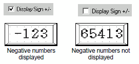
Display Sign
Set to display negative numbers.
This can be set when the [Data Type] is [Dec].
For example, When writing "-123"
Source Range / Display Range
Min. Value/Max. Value
Select the Source Range and Display Range for the numeric data to be displayed.
If [Input Specification] or [Display Specification] is [Constant], minimum values / maximum values can be entered.
If [Address] is set, specify the word address where the min/max value will be stored.
The setting range differs according to [Data Type], [Source Sign], and [Display Sign +/-].
16 bit
|
Data Type |
Sign +/- |
Source Range |
Display Sign +/- |
Display Range |
|---|---|---|---|---|
|
Dec |
None |
0 to 65535 |
Disable |
0 to 65535 |
|
Enable |
-32768 to 32767 |
|||
|
2's Complement |
-32768 to 32767 |
Disable |
0 to 65535 |
|
|
Enable |
-32768 to 32767 |
|||
|
MSB |
-32767 to 32767 |
Disable |
0 to 65535 |
|
|
Enable |
-32768 to 32767 |
|||
|
Hex |
None |
0 to 65535 |
— |
0 to FFFF(h) |
|
2's Complement |
-32768 to 32767 |
— |
0 to FFFF(h) |
|
|
MSB |
-32767 to 32767 |
— |
0 to FFFF(h) |
|
|
Oct |
None |
0 to 65535 |
— |
0 to 177777(o) |
|
2's Complement |
-32768 to 32767 |
— |
0 to 177777(o) |
|
|
2's Complement |
-32767 to 32767 |
— |
0 to 177777(o) |
|
|
BCD |
— |
0 to 9999 |
— |
0 to 9999 |
|
Bin |
None |
0 to 65535 |
— |
0 to FFFF(h) |
|
2's Complement |
-32768 to 32767 |
— |
0 to FFFF(h) |
|
|
MSB |
-32767 to 32767 |
— |
0 to FFFF(h) |
32 bit
|
Data Type |
Sign +/- |
Source Range |
Display Sign +/- |
Display Range |
|---|---|---|---|---|
|
Dec |
None |
0 to 4294967295 |
Disable |
0 to 4294967295 |
|
Enable |
-2147483647 to 2147483647 |
|||
|
2's Complement |
-2147483648 to 2147483647 |
Disable |
0 to 4294967295 |
|
|
Enable |
-2147483647 to 2147483647 |
|||
|
MSB |
-2147483647 to 2147483647 |
Disable |
0 to 4294967295 |
|
|
Enable |
-2147483647 to 2147483647 |
|||
|
Hex |
None |
0 to 4294967295 |
— |
0 to FFFFFFFF(h) |
|
2's Complement |
-2147483648 to 2147483647 |
— |
0 to FFFFFFFF(h) |
|
|
MSB |
-2147483647 to 2147483647 |
— |
0 to FFFFFFFF(h) |
|
|
BCD |
— |
0 to 99999999 |
— |
0 to 99999999 |
|
Bin |
None |
0 to 4294967295 |
— |
0 to FFFFFFFF(h) |
|
2's Complement |
-2147483648 to 2147483647 |
— |
0 to FFFFFFFF(h) |
|
|
MSB |
-2147483647 to 2147483647 |
— |
0 to FFFFFFFF(h) |
|
|
Float |
— |
-9.9e16 to 9.9e16 |
— |
-9.9e16 to 9.9e16 |
![]()
The Source Range and Display Range define how to automatically convert values acquired for display. Even if values outside the source range are obtained, the values are automatically converted and displayed with the values outside the display range.