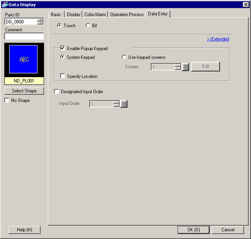
Data Entry Methods
Select the method that will change the Data Display to input state (cursor display state).
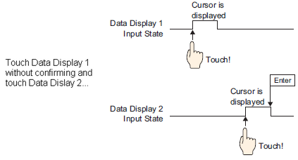
Touch
When the Data Display is touched, it will change to the Allow Input state.

![]()
If you touch a Data Display while inputting data into another Data Display, the input data will revert to its previous data, and the most recently touched Data Display will enter the Allow Input state.
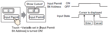
Bit
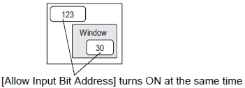
When the Allow Input Bit Address is ON, the Data Display is in the Allow Input state.
![]()
If the [Allow Input Bit Address] is turned OFF while inputting data in a Data Display, the Allow Input state is canceled and the input data is erased.
Touch
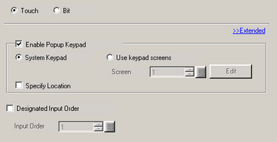
Enable Popup Keypad
Select to display a pop-up keypad when you touch the Data Display.

Keypad Type
System Keypad
Use the standard keypad registration for GP-Pro EX. Use this in normal cases.
Use keypad screens
Create a user-defined keypad with the Keypad part. Pre-define the keypad in the Keypad screen. This keypad allows for customized input.
![]() 15.4.2 Procedure - Customizing the Keypad Layout / Popup
15.4.2 Procedure - Customizing the Keypad Layout / Popup
System Keypad
Display the prepared standard keypad registration in GP-Pro EX.
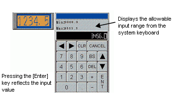
![]()
The input range displayed on the system keypad varies depending on whether or not the Alarm Settings are being used.
If there are no Alarm Settings, the keypad shows the [Display Range] minimum and maximum values
If there are Alarm Settings, the keypad shows the [Alarm Settings] lower and upper limit values
When defining the alarm settings, the upper and lower limits are displayed as the input range.
When the [Scaling Settings] check box is selected, even if no alarm is set up, the upper limit and lower limit are displayed as the input range.
When neither [Alarm Settings] nor [Scaling Settings] are set up, the upper limit and lower limit are displayed as the input range, for the specification data type and the display digit number.
When [Data Type] is set to [32 Bit Bin], the display range and the source range (or the alarm range) during inputs are not displayed.
When [Data Type] is [32 Bit Float], for cases in which Alarm Settings are not configured, the source range is not displayed.
Use keypad screens
Screen
Set the number of pre-defined custom keypad screen.
Edit
The custom keypad screen specified in the [Screen Number] opens. If no custom keypad is specified, [New Screen] dialog opens.
Specify Location
Used to specify the display position for the pop-up keypad. If selected, the pop-up keypad Display Area can be selected and moved after the Data Display is positioned.
![]()
When you group a Data Display with other parts, you cannot select or move the pop-up keypad display area.
Designated Input Order
When entering data into multiple Data Displays in sequence, select the order in which each display enters the input state.
![]() 14.13 How Data Input Order Works
14.13 How Data Input Order Works
Input Order
Select the order, from 1 to 384, in which the Part will enter the input state.
Bit
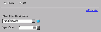
Allow Input Bit Address
When the bit address set here turns ON, the Data Display enters the input state.
Input Order
Number the Data Displays from 1 to 384 in the order that they will enter the Allow Input state if the [Allow Input Bit Addresses] of multiple Data Displays turn ON at the same time (when a bit address has been registered to multiple Data Displays, or when different bit addresses turn ON at the same time).
![]()
If more than one [Allow Input Bit Address] is turned ON at the same time, the Data Displays will enter the input state according to their [Input Order] settings. If the [Input Order] settings are the same, the input state order will be determined by the order the Data Displays were placed.
If the [Allow Input Bit Address] of Data Displays placed on the Base Screen and Window Screen turn ON at the same time, the Base Screen will have a higher priority for the input state than the Window Screen. When placing Data Displays on both the Base and Window screens, make sure to set a different [Allow Input Bit Address] for each.
![]()
When Visibility Animation is set for a Data Display [Numeric Display], it will operate as described below.
When it is invisible, it cannot be activated by touch.
If a Bit operation is executed when it is visible, the input box will appear, and if the Popup Keypad is set up, the Popup Keypad will also appear.
If a Bit operation is executed when it is invisible, it will remain invisible and the input box will not appear. If a bit operation is executed and the bit is still on when the object becomes visible again, the input box will also appear. When there is already a Data Display in the input state, the input box will enter the input state when input in the current Data Display is complete.
When it changes from visible to invisible in the input state, the input state will be canceled. If a popup keypad is being displayed, the popup keyboard also becomes invisible.
When the Designated Input Order is enabled, the next Data Display enters the input state. Also, if a Data Display is invisible when it comes to its turn in the input order, the input box does not appear and the next Data Display enters the input state.