The following lists the data contents stored in the LS9000 Area.
|
Display Unit Internal Address |
Description |
Introduction |
H System Variable |
|---|---|---|---|
|
LS9000 to |
Display Historical Graph Data |
Historical data numbers and data values |
- |
|
LS9100 to |
Script Process |
Script error code |
- |
|
LS9200 to |
CSV Data Transfer Feature |
Number and file number of CSV data files transferred by the Condition Name Search Feature |
- |
|
LS9210 to |
Reserved |
Reserved |
- |
|
LS9220 to |
|||
|
LS9230 to |
VM Unit serial mouse feature |
Serial mouse touch state and coordinates |
- |
|
LS9235 to |
Touch Coordinates |
Touch coordinates on display unit screen |
- |
|
LS9240 to |
Reserved |
Reserved |
- |
|
LS9260 to |
|||
|
LS9272 - LS9274 |
MAC Address |
MAC Address |
- |
|
LS9280 to |
Reserved |
Reserved |
- |
|
LS9290 to |
|||
|
LS9300 to |
Security feature |
Security Level |
- |
|
LS9310 to |
Day of the Week |
Day of the Week |
#H_CurrentDayofTheWeek |
|
LS9320 to |
Reserved |
Reserved |
- |
|
LS9330 to |
|||
|
LS9350 to |
RGB 2ch Serial Mouse Feature |
Touch state and coordinates of RGB unit serial mouse |
- |
|
LS9370 to |
Reserved |
Reserved |
- |
|
LS9400 to |
Communication Cycle Time |
Communication cycle time of device/PLC |
[PLC*]#H_DriverCycleTime*1 |
|
LS9528 to |
Reserved |
Reserved |
- |
|
LS9550 to |
Communication Scan ON/OFF Control |
Device/PLC communication scan ON/OFF |
[PLC*]#H_ScanOffControl |
|
LS9558 to |
Reserved |
Reserved |
- |
|
LS9560 to |
Communication Scan ON/OFF Status |
Device/PLC communication scan status |
[PLC*]#H_ScanOffStatus |
|
LS9568 |
Reserved |
Reserved |
- |
|
LS9800 to LS9815 |
Alarm Polling Cycle Information |
Actual measured polling time and average time of each block when extended alarm is enabled |
- |
|
LS9920 to |
Reserved |
Reserved |
- |
|
LS9930 to |
|||
|
LS9940 to LS9943 |
|||
|
LS9944 |
|||
|
LS9946 |
|||
|
LS9950 |
Reserved |
Reserved |
- |
|
LS9970 to LS9999 |
*1 [*] = name of Device/PLC
*2 H system variables store content from the 33rd item and beyond.
Details About Each Address
Display Historical Graph Data
In the [Historical Trend Graph] part, select the [Display Historical Data] check box to display the data numbers and values for the oldest and newest data on the graph display area.
![]() 19.8.3 Display Historical Data
19.8.3 Display Historical Data
Script Process
The following data is stored in Script process area.
|
LS9100 |
Extended script error code |
|
LS9101 |
Extended script error status |
|
LS9102 to LS9109 |
Reserved |
|
LS9110 |
Global D Script error code |
|
LS9111 |
Global D-Script error status |
|
LS9112 to LS9119 |
Reserved |
|
LS9120 |
D Script error code |
|
LS9121 |
D Script error status |
|
LS9122 to LS9129 |
Reserved |
|
LS9130 |
Data Storage Mode
|
|
LS9131 |
Reserved |
|
LS9132 |
CF list status, SD list status |
|
LS9133 |
CF read status, SD read status |
|
LS9134 |
CF write status, SD write status |
|
LS9135 |
CF delete status, SD delete status |
|
LS9136 |
CF rename status, SD rename status |
|
LS9137 |
CF CSV read status, SD CSV read status |
|
LS9138 |
USB list status |
|
LS9139 |
USB read status |
|
LS9140 |
USB write status |
|
LS9141 |
USB delete status |
|
LS9142 |
USB rename status |
|
LS9143 |
USB CSV read status
|
|
LS9144 to LS9149 |
Reserved |
|
LS9150 |
Block ring shift status |
|
LS9151 |
Block clear shift status |
|
LS9152 |
Block memory comparison status |
|
LS9153 |
Block memory search status |
|
LS9154 to LS9199 |
Reserved |
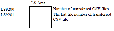
CSV Data Transfer Feature
Stores the number and the file number of CSV data transferred by the Condition Name Search Feature. The search is only possible when the search string is a perfect match for the condition name.
Spaces indicate different file names and can cause errors. When data transfer is completed, the status and number of transferred files displays. The last transferred file numbers are written in the GP internal device Special Areas LS9200 and LS9201. (The Special Areas are read-only.)
VM Unit serial mouse feature
Using DVI/VM unit, this feature stores the touch status and the touch coordinates when sending the touch coordinates to a PC by serial communication.
![]() 28.10.7.4 Emulate Touch Output
28.10.7.4 Emulate Touch Output
Touch Coordinates
Stores the touch coordinates on a display screen.
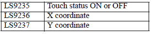
The display coordinate range depends on the display unit's panel resolution. The display coordinate range is fixed, no matter if you set up the display unit for portrait or landscape orientation. When using portrait orientation, you cannot store Y coordinates outside the following range.
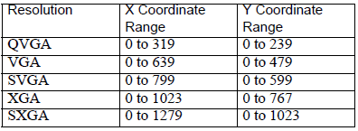
![]()
The following operations do not store coordinates, even if touch is involved
Offline Mode Operations
Screen Data Transfer Operations
System Menu Operation
Brightness/Contrast Control Bar Operations
Depending on the model, even if you touch outside the display area, there are cases where the value is retrieved. In such cases, the retrieved value will be outside the display range.
When calibration is not properly set with the display unit of the analog touch panel technology, numerical values outside the range may be obtained.
When two points are touched at the same time with the display unit of the analog touch panel technology, the mid-point between these coordinates is stored.
When [two-point touch] is set with the display unit of the analog touch panel technology, only the first touch coordinate point is stored.
When using GP-Viewer EX, you cannot retrieve touch coordinates.
When communication type is only Memory Link with Ethernet Multilink, the master display unit coordinates are stored.
When one-point touch (no slide) is set with the display unit of the analog touch panel technology or the display unit of the matrix touch panel technology
, for cases in which the inside of the touch area is touched while the finger is moved, when it reaches outside the touch area, the touch status is turned OFF the moment it moves outside the area. For WinGP, touch remains ON despite going out of range.
In such cases, the area's final touch coordinates are stored.
The following positions are the starting coordinate point when a display unit's orientation is set to [Portrait].
Display units except GP-4100 Series: Bottom-left of the screen (0,0)
GP-4100 Series: Top-right of the screen (0,0)
For more details, please refer to the following.
![]() 3.9.1 Restrictions for Screen Display
3.9.1 Restrictions for Screen Display
MAC Address
The MAC addresses for display units are stored as hexadecimal values in LS9272 - LS9274, starting from the first octet.
Security feature
When bit 0 of LS9300 toggles from OFF to ON, the security level stored in LS9301 will be changed to 0.
After the Security Level Clear occurs, return LS9300's 0 bit to OFF. (LS9301 is read-only.)
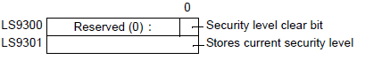
Also, it stores the current security level and the security level of the screen to be displayed
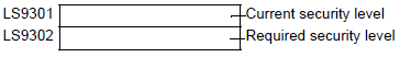
LS9301 and LS9302 are read-only. When there is a password request in LS9302, the security level is stored and the value returns to 0 when the password input is complete.
Day of the Week
Stores the current value of the day of the week. The day is calculated from the Year, Month, and Day of the display unit's onboard IC (RTC) clock. The values stored in LS9310 are as follows.
|
Numeric Value |
Description |
|---|---|
|
0 |
Sunday |
|
1 |
Monday |
|
2 |
Tuesday |
|
3 |
Wednesday |
|
4 |
Thursday |
|
5 |
Friday |
|
6 |
Saturday |
|
After 7 |
Unused |
Updates are performed when the IC clock date is changed. Because the writes do not occur regularly, when parts change in this area, this area is not updated until the IC clock date changes.
RGB 2ch Serial Mouse Feature
When the RGB unit is set to display 2 channels at the same time and is sending the touch coordinates to a PC by serial communication, it stores the touch status and coordinates.
![]() 28.10.7.4 Emulate Touch Output
28.10.7.4 Emulate Touch Output
Communication Cycle Time - 4 drivers x 32 devices
Stores polling cycle time (in milliseconds) of the configured Device/PLC
![]() 5.4.13 System Settings [Peripheral List] Settings Guide
5.4.13 System Settings [Peripheral List] Settings Guide
![]()
H system variables store content from the 33rd item and beyond.
Communication Scan ON/OFF Control - 4 drivers X 32 devices
Controls whether to run or stop the communication scan with the configured Device/PLCs.
![]() 5.4.13 System Settings [Peripheral List] Settings Guide
5.4.13 System Settings [Peripheral List] Settings Guide
![]()
H system variables store content from the 33rd item and beyond.
Communication Scan ON/OFF Status - 4 drivers X 32 devices
Stores the communication scan status of the configured Device/PLC
![]() 7.3.2 Procedure - Confirming the Communication State
7.3.2 Procedure - Confirming the Communication State
![]()
H system variables store content from the 33rd item and beyond.
Alarm Polling Cycle Information
Stores the actual measured polling time and average time of each block when extended alarm is enabled. Also sets the Polling Time Exceeded bit to 1 when the actual polling time exceeds the configured time.