![]()
Please refer to the Settings Guide for details.
 13.8 Lamp Settings Guide
 For details on how to draw parts and define the address, shape, color, and labels, please see the "Part Editing Procedure".
8.7.1 Editing Parts
![]()
Please refer to the Settings Guide for details.
![]() 13.8 Lamp Settings Guide
13.8 Lamp Settings Guide
For details on how to draw parts and define the address, shape, color, and labels, please see the "Part Editing Procedure".
![]() 8.7.1 Editing Parts
8.7.1 Editing Parts
The following procedure shows how to display the direction in which a crane is moved (right, left, or stop) and the error notification bit state in different colors using a single lamp. Using the following method, you can display a total of 5 states, including all bits OFF.
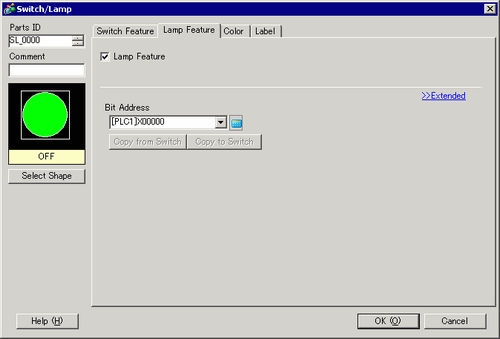
From the [Parts (P)] menu, point to [Switch Lamp (C)] and select [Lamp (L)] or click ![]() to place a lamp on the screen.
to place a lamp on the screen.
Double-click the placed lamp. The Switch/Lamp dialog box appears. Click [Extended].
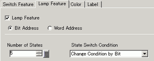
Set the [Number of States] and [State Switch Condition]. Setting the [Number of States] to 3 or more allows you to set [State Switch Condition]. (For example, [Number of States] = 5, [State Switch Condition] = Change state by bit)
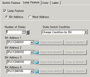
Set [Bit Address 1]. From From the [Address Input] dialog box, select the device/PLC, set X101 as the device address, and click [Ent]. (For example, X101)
Also, set [Bit Address 2] to [Bit Address 4] as follows.
(For example, [Bit Address 2] X102, [Bit Address 3] X103, [Bit Address 4] M100)
![]()
You can define each [State] by setting its corresponding bit address to either ON (1) or OFF (0).
State |
Description |
|||
|---|---|---|---|---|
Bit Address 4 |
Bit Address 3 |
Bit Address 2 |
Bit Address 1 |
|
[State 0] |
0 |
0 |
0 |
0 |
[State 1] |
0 |
0 |
0 |
1 |
[State 2] |
0 |
0 |
1 |
0 |
[State 3] |
0 |
1 |
0 |
0 |
[State 4] |
1 |
0 |
0 |
0 |
When multiple bits are ON, the lamp with the highest priority is displayed.
The order of lamp priority from highest to lowest is [Bit Address 1], [Bit Address 2], [Bit Address 3], [Bit Address 4].
In [Select Shape], select the lamp shape for each [State].
Click the [Color] tab. In the [Select State] list, select [State 0] and define its [Display Color].
[State 0] is the state where all the specified bit addresses are OFF.
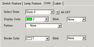
Select [State 1] in [Select State] and set the [Display Color]. [State 1] is the state where the specified Bit Address X101 is ON.
Set [Display Color] for [State 2] to [State 4].
![]()
Depending on the shape, the color setup procedure may differ from the procedure described above. Click [Select Shape]. The [Select State] window appears. Select each state and click [Open] to select a shape and color.
Depending on the shape, you may not be able to change the color.
Click the [Label] tab. Define the label to appear on the Lamp. Specify the font type and size, and then in the rectangular field type the text to display. Click [OK].
![]()
When you select a lamp and press the [F2] key, you can directly edit the text on the label.