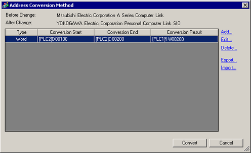
On the [Change Device/PLC] dialog box, click [Change Specifying Address Conversion], and the following dialog box appears. You can specify an Address Conversion Range when changing device/PLC models.

Before Change
Displays the maker and series of the old PLC.
After Change
Displays the maker and series of the new PLC.
Type
Displays [Word] or [Bit], depending on which is the conversion address type.
Conversion Start
Displays the start value of the device address used before the address conversion.
Conversion End
Displays the end value of the device address used before the address conversion.
Conversion Result
Displays the start value of the device address used after the address conversion.
Add/Edit
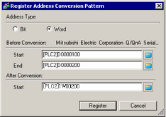
Add/edit new settings for an address conversion pattern. The following dialog box appears.

Address Type
Choose conversion address type from [Bit] or [Word].
Before Conversion
Displays the maker and series of the old PLC.
Start
Set the source PLC and the start address.
End
Set the source PLC and the end address.
After Conversion
Displays the maker and series of the new PLC.
Start
Set the destination PLC and the start address.
Delete
Delete the address conversion pattern.
Export/Import
Read (Import) or output (Export) the contents of an Address Conversion Pattern.

Import
You can use a previously saved file in CSV format to create an address conversion pattern file (see Export).
Address conversion pattern files can be used in a different project by importing them.

![]()
When importing a CSV file, make sure it matches the address conversion pattern format. If the formats do not match, the file will not be successfully imported.
Specify the [Delimiter Setting(U)] according to the separator character used in the CSV file to be imported.
You can export registered address conversion patterns to other applications by saving them in CSV format.
The saved file can then be edited in Microsoft Excel or in other spreadsheet software.

![]()
This setting can be used when there are multiple address conversion patterns.
The exported CSV file can be edited in a spreadsheet program such as Microsoft Excel.
Sample Output to a CSV File
Export data's CSV format is displayed as follows.
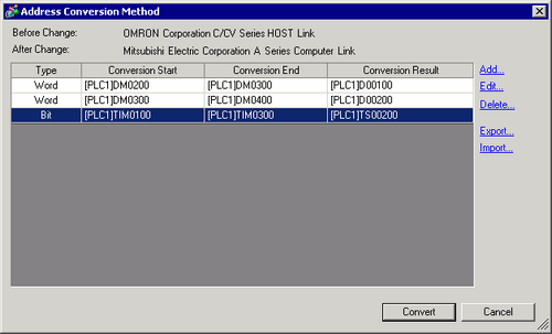
Address conversion patterns before export

The CSV (comma-deliminated) file created by exporting the above file
Pattern List
File Version,1,0
OMR_CSIO
MIT_ACPU
0,[PLC1]DM0200,[PLC1]DM0300,[PLC1]D0100
0,[PLC1]DM0300,[PLC1]DM0400,[PLC1]D0200
1,[PLC1]TIM0100,[PLC1]TIM0300,[PLC1]TS0200
Pattern List
Key Name*1
File Version
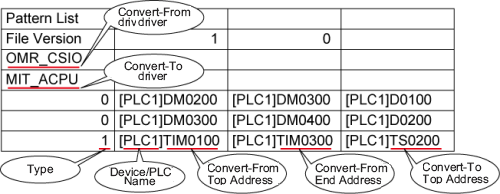
The version number of the file.
It is automatically set when a file is exported.
OMR_CSIO
Convert-From driver
MIT_ACPU
Convert-To driver
0,[PLC1]DM0200,[PLC1]DM0300,[PLC1]D0100
[Type]*2, [Device/PLC Name] Convert-From Start Address,[Device/PLC Name] Convert-From End Address, [Device/PLC Name] Convert-To Start Address
0,[PLC1]DM0300,[PLC1]DM0400,[PLC1]D0200
[Type]*2, [Device/PLC Name] Convert-From Start Address,[Device/PLC Name] Convert-From End Address, [Device/PLC Name] Convert-To Start Address
1,[PLC1]TIM0100,[PLC1]TIM0300,[PLC1]TS0200
[Type]*2, [Device/PLC Name] Convert-From Start Address,[Device/PLC Name] Convert-From End Address, [Device/PLC Name] Convert-To Start Address
When the above CSV file is represented in tabular format, it looks as follows.

*1 This is the special text used to identify the address conversion pattern's CSV file.
*2 [Word Address]:0, [Bit Address]:1