Please refer to the Settings Guide for details.
20.12.1.2 Alarm Settings (Block 1) - Bit Monitoring
20.12.2.1 Show History - Basic Settings/Basic
For details on how to draw parts and define the address, shape, color, and labels, please see the "Part Editing Procedure".
8.7.1 Editing Parts
When the Monitoring Bit Address turns ON, the Alarms are displayed together with their trigger date/time. When the Monitoring Bit Address turns OFF, the recovery time is added on the same row.
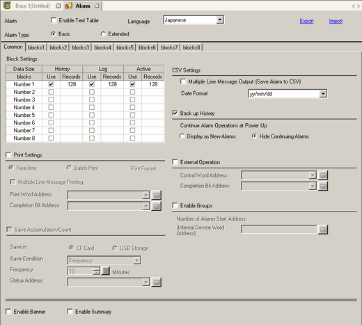
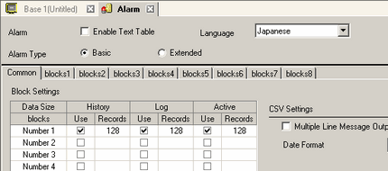
From the [Common Settings (R)] menu, select [Alarm (A)], or click . The following screen appears. In [Language], select the alarm message display language.
In the Block Settings, select the check box for the desired display mode (History/Log/Active) for the block to which the message is registered, and set the number of messages stored as history for each mode.
Select [Backup History] and define [Hide Continuing Alarms].
When the [Backup History] check box is not selected, the alarm history data will be erased when the display unit is turned OFF or reset.
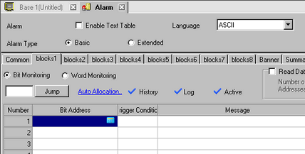
From the [Block1] tab, select [Bit Monitoring].
In [Bit Address], set the bit address to monitor the alarm trigger.
In the [Trigger Condition] cell, select whether the alarm is triggered when the Monitoring Bit Address turns ON or turns OFF.
In the [Message] cell, input the alarm message that will display when the alarm is triggered.
Up to 160 single-byte characters can be registered in a single Alarm Message.
When the [Enable Text Table] check box is selected, you can change the displayed message language even while the system is running.
18.3 Changing Text to Other Languages
Alarm settings can be exported or imported in CSV format.
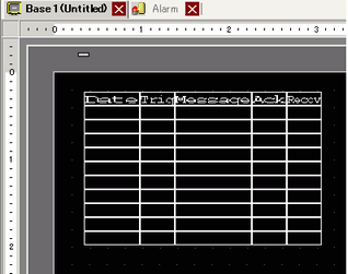
Open the screen editor and set the Alarm part which will display the Alarm. From the [Parts (P)] menu, select [Alarm (A)], or click and place the part on the screen.
Alarm parts look different on the editor screen and on the display unit. The borders and item names such as "Date" and "Trig" shown on the editor screen do not appear on the display unit.
To display borders, in the alarm part's [Display] tab configure the [Border] setting. To display item names, in the alarm part's [Item] tab configure the [Extended] settings.
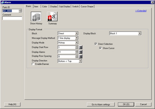
Double-click the placed Alarm. The Alarm dialog box appears.
Specify the block to display in Alarm parts and select [History] in the [Display Mode].
When [Multiple line display] is selected in the [Message Display Method], messages can be displayed on a separate line from other information such as the trigger date or time. Since the message display area expands, you can quickly verify contents of long messages.
Set the [Display Start Row], [Display Alarms] and [Display Row Spacing].
As needed, use the [Item] tab, [Color] tab, and [Display] tab options to change alarm message's number of display characters, text color, background color, font, and size.
The maximum number of characters allowed on one line and on the lines of one screen are decided by the type of display unit and [Size].
If your message is wider than the display area, the portion that exceeds the area is truncated and is not displayed. However, if your model supports the banner display of alarm history and [Enable Banner] is selected in the [Display Settings] tab, or if you are using GP-4100 Series (Monochrome Model), you can display longer messages as messages scroll across the screen like a marquee.