
Set the Global Window display settings.
Global Window Operation
Select the action of the Global Window, which displays on all screens: [Disable], [Direct], or [Indirect].
Disable
Does not use a Global Window.
Direct
Displays the Window Screen number to display and its position in a fixed state.
Control the display with address LS16 in the display unit's internal device, or the device/PLC associated with the system data area.
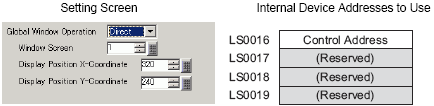
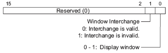
Control Address
Controls the display of a Global Window. If you turn ON Bit 0, a Window is displayed.
![]()
To use a system data area on the device/PLC, use four sequential words from the assigned address.
![]() 5.4.6 System Settings [Display Unit] - [System Area] Settings Guide
5.4.6 System Settings [Display Unit] - [System Area] Settings Guide
Window Screen Number
Set the Global Window screen number from 1 to 2000.
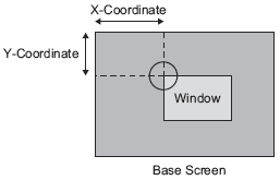
Display Position X-Coordinate/Y-Coordinate
Set the Global Window display position. Even if the screen changes, the Window is displayed in the same position. The coordinate specified here is the top left corner of the Window.
![]()
For all models except for the GP4000 series, LT4000 series and the IPC series, set X-coordinate in four pixel increments. If the display position is not specified by 4 dots, the position is automatically corrected by 4 dots to the left of the specified coordinate to display the Global Window.
Indirect
Set the Window Screen number to display and its position by storing data in the display unit's internal device addresses (LS16 to LS19). If you assign a system data area to the device/PLC, you can switch Window Screens or change the display position from the device/PLC.
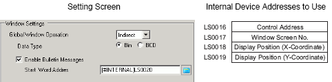
Control Address
Controls the display of a Global Window. If you turn ON Bit 0, a Window is displayed.
Window Screen
Specify the number of the Window Screen you want to display from 1 to 2000.
Display Position X-Coordinate/Y-Coordinate
Set the Global Window display position. If you change the value to store in the address, you can move the Window. The coordinate specified here is the top left corner of the Window.
![]()
To use a system data area on the device/PLC, use four sequential words from the assigned address.
![]() 5.4.6 System Settings [Display Unit] - [System Area] Settings Guide
5.4.6 System Settings [Display Unit] - [System Area] Settings Guide
Data Type
Select the type of data to store in the address from [Bin] or [BCD].
Specify whether to use the bulletin message of the message display.
![]()
For more information about this function, please refer to the following.
![]() 17.5 Displaying the Same Message on Multiple Display Units (Bulletin Messages)
17.5 Displaying the Same Message on Multiple Display Units (Bulletin Messages)
Start Word Address
Select the start internal address (LS area, USR area or memory link system area) which will trigger the message display.
As per the following format, values are used with the specified internal address.
|
Address |
Description |
|
Specified Address+0 |
Display Trigger |
|
Specified Address+1 |
Window Number |
|
Specified Address+2 |
X coordinate of the window display position |
|
Specified Address+3 |
Y coordinate of the window display position |
Additions in the Specified Address conform to the device size.
When it is a 16-bit device, addition is based on words.
When it is a 32-bit device, addition is based on double words.
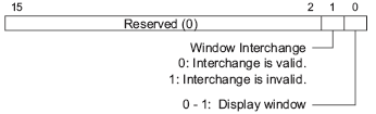
Specified Address+0: Display Trigger
Set Display/Delete settings of the window screen.
![]()
Specify bit 0 as a message display or message clear trigger.
The same bit is used regardless of the size of the specified device (16 bit/32 bit device).
If a bit other than the display/delete bit is selected, it will be ignored.
It interacts with the window number, window display position (X coordinate), and window display position (Y coordinate).
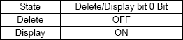
The action in each state is as follows.
Delete
Turn OFF the window control in the system data area.
Display
Set the values of window number and window display positions (X and Y coordinates) of the specified address to the window number and window display positions (X and Y coordinates) of the system data area.
Turn ON the window display of the window control.
Enable the window interchange of the window control.
Example: Specified internal address is USR0100
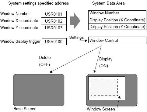
Specified Address+1: Window Number
Specify the window screen number.
Specified Address+2: X coordinate of the window display position
Specify the X coordinate of the window display position.
Specified Address+3: Y coordinate of the window display position
Specify the Y coordinate of the window display position.