LT3000 Series
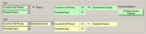
Channel
Select an input type from the bottom section. The I/O types in the top section are fixed to [Counter A (A Phase)] and [Counter B (B Phase)].
Displays the terminal mapping.
Match
Select when synchronizing output.
Terminal Attributes
Click [2 Phase Counter Settings] to specify detailed settings.
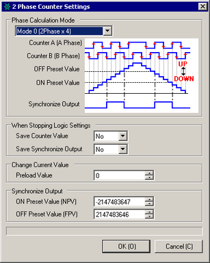
Phase Calculation Mode
Select a phase calculation mode.
Save Counter Value
Select whether or not you want to retain counter values when the logic is stopped.
Save Synchronize Output
Select whether or not you want to retain the synchronize output state when logic is stopped.
Preload value
Enter the value you want to set as the current value for counter.
ON Preset Value / OFF Preset Value
Enter the value that is used to change the output value when using Synchronize Output.
LT4000 Series
Select [2 Phase Counter] when using 2-phase high speed counter.
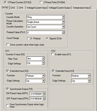
Counter Mode
Select a counter mode.
Linear
Performs count up or count down one time. The count operation ends when the Current Counter Value reaches either the minimum or maximum value. To start counting again, clear the Current Counter Value with the system variable (#L_ExIOCntInCtrl).
Ring
Repeatedly runs the count operation. When the counter reaches the maximum or minimum value in the counting range, the counter is reset to either the minimum or maximum value then continues counting.
Sampling
Pulse count and signal frequency within the Time Base period is stored in the Current Counter Value. When the period set in the Time Base elapses, the Current Counter Value is updated.
Phase Calculation Mode
Select a phase calculation mode.
Counter Operation
Select a counter operation.
Preload Value
Enter the value you want to set as the current value for counter. Select when [Counter Mode] is set to [Ring] or [Linear].
Count Range
Select the range for the count. Select when [Counter Mode] is set to [Ring] or [Linear].
Data Type
Select the count unit. Select when [Counter Mode] is set to [Sampling].
Pulse Count
Pulses entered within the Time Base period are stored in the Current Counter Value.
Frequency
The pulse signal frequency input within the Time Base period is stored in the Current Counter Value. The unit is in Hz.
Time-Base
Enter the intervals at which you want to count the input signal's pulses or frequency. Select when [Counter Mode] is set to [Sampling].
Save counter value when logic stops
Select whether or not you want to retain counter values when the logic is stopped.
Counter A Input
Configure the Counter A Input settings.
Filter Time
Select the Filter Time for the input signal. Counts input signals that change ON/OFF at intervals longer than the Filter Time.
Edge Settings
Select the timing for counting input signals.
Up
Counts the positive transition of pulse inputs.
Down
Counts the negative transition of pulse inputs.
Enable Input
Select when using enable input.
Extended Input
Select when using extended input. You can configure this option for CH1 and CH2 separately.
Feature
Select the function to run when you receive a signal from the input terminal.
Preload
Writes the Current Counter Value to the system variable (#L_HSC*_PLV).
Prestrobe
Stores the Current Counter Value in the system variable (#L_HSC*_PSV).
Marker
Clears the Current Counter Value to zero (0).
Edge Settings
Selects the timing on when to run the function.
Up
Runs the function when a positive transition in the Extended Input is detected.
Down
Runs the function when a negative transition in the Extended Input is detected.
Both
Runs the function when either a positive or negative transition in the Extended Input is detected.
Synchronize output
Select when synchronizing output.
ON Preset Value / OFF Preset Value
Enter the value that enables changing the Synchronize Output.
Save Synchronize Output when logic stops
Select whether or not you want to retain the synchronize output state when logic is stopped.