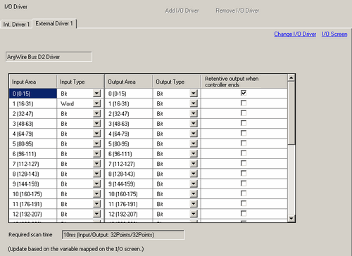
Input Area
Area you can use for inputs is divided into 28 x 16-bit areas.
The Input Area field displays the input area number and associated bits in brackets "input area number (start bit - end bit)". You cannot edit the Input Area.
Input Type
Select the input type from either [Bit] or [Word].
Output Area
Area you can use for outputs is divided into 28 x 16-bit areas.
The Output Area field displays the output area number and associated bits in brackets "output area number (start bit - end bit)". You cannot edit the Output Area.
Output Type
Select the output type from either [Bit] or [Word].
Retentive output when controller ends
Select whether or not you want to retain output values when the logic program stops. Select the check box to retain outputs.
![]()
The following operations will reset outputs.
Turn OFF the display unit.
Restart the display unit.
Go to offline mode.
Transferring a project.
Required scan time
Displays the scan time with the current settings and I/O points as : XX milliseconds (Input/Output: YY Points/ZZ Points).
![]()
The required scan time is calculated as shown in the following table.
|
Area in Use*1 |
I/O Points |
Required scan time |
|
Unused or 0 to 1 |
Input/Output: 32Points/32Points |
10 ms |
|
2 to 3 |
Input/Output: 64Points/64Points |
10 ms |
|
4 to 7 |
Input/Output: 128Points/128Points |
10 ms |
|
8 to 11 |
Input/Output: 192Points/192Points |
14 ms |
|
12 to 15 |
Input/Output: 256Points/256Points |
18 ms |
|
16 to 19 |
Input/Output: 320Points/320Points |
22 ms |
|
20 to 23 |
Input/Output: 384Points/384Points |
26 ms |
|
24 to 27 |
Input/Output: 448Points/448Points |
30 ms |
*1 "Area in Use" refers to the largest area number mapped to a variable.
For example, when you map I3 (bit 35) of Input Area 2 (32-47), and Q3 (bit 163) of Output Area 10 (160-175), the "Area in Use" is 10.
When the send/receive values between the first and second cycles match, the I/O status is updated. When the data values had changed in the second cycle, the I/O status is not updated.
The approximate communication time for one cycle is as follows.
|
I/O Points |
Approximate communication time |
|
Input/Output: 32Points/32Points |
1.7 ms |
|
Input/Output: 64Points/64Points |
2.7 ms |
|
Input/Output: 128Points/128Points |
4.8 ms |
|
Input/Output: 192Points/192Points |
6.8 ms |
|
Input/Output: 256Points/256Points |
8.9 ms |
|
Input/Output: 320Points/320Points |
10.9 ms |
|
Input/Output: 384Points/384Points |
13.0 ms |
|
Input/Output: 448Points/448Points |
15.0 ms |
From the [System Settings], in the [Logic Programs] page, when [Register Variable] uses the [Address Format] option, the required scan time is 30 milliseconds as all I/O are mapped.