No scan time can be guaranteed when a program is being uploaded.
No scan time can be guaranteed when a CF/SD card is being read.
When an error arises in the logic or the I/O driver, the scan time is delayed by approximately 10ms.
When many devices are connected to the network, the scan time may be delayed.
It is recommended to physically separate the network into a control network, an information network, and others if necessary.
To be more specific, configure a PC with two network cards and configure the control network that includes the AGP on one card and configure the information network on the other. In other words, separate the network into two groups on the PC.
When movies are recorded/played using the multimedia function while the logic is in use, movie recording/playback may stop.
Please note that data updates between a device/PLC and the logic program are not synchronized when the device/PLC address (excluding internal addresses) is used in the logic program.
The data value is sometimes undefined when the logic program starts, and is not updated until communication with the device/PLC is established. Check that the device/PLC address data has been updated before using it in the logic program.
For example, a special relay (always on) is used for a device/PLC.
Connection Device: Special relay (always on)
Logic program: Use the special relay in the logic program and check that the special relay is on before using the device/PLC address. If there are several devices/PLCs, a different relay is required for each device.
For logic programs, you cannot use disabled addresses to read devices/PLC. For unreadable addresses, refer to the "GP-Pro EX Device Connection Manual".
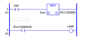
If the same address (except for variables) is specified as a word address and as a bit address and used in multiple instructions, data between the word and bit specified addresses may be different in the same scan.
For example, the NO instruction [PLC1]D0000.00 will not show the data set in the MOV instruction [PLC1]D0000. Even if "1" is written in the variable "Data", the change is shown on [PLC1]D0000.00 only after a few scans.

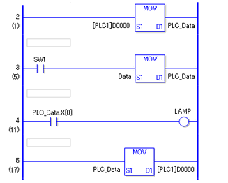
To avoid this problem, do the following.
Specify bits after moving data from the address to a variable (rung 2)
When updating data on the device/PLC as a result of the logic program, make sure you use the MOV instruction (rung 5)

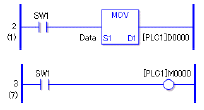
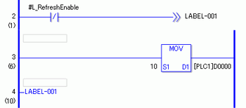
If the logic program includes operations for writing to the device/PLC address, the following phenomenon may occur, depending on the communication speed and the number of device/PLC addresses to write to:
When the display unit starts up, parts set up with the device/PLC address do not display.
Change screen operations take extra time.
Writing to the device/PLC fails.

