This section explains how to describe a logic program using IL.
|
Instruction Name |
Description |
illustration |
|
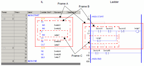
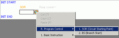
SOR |
Indicates a starting point of a circuit. From an SOR to the next SOR is one circuit. |
Frame A |
|
BS |
Indicates a starting point of a branch. The section from BS to B is the upper portion of the branch in the ladder configuration. |
Frame B |
|
B |
Indicates a branch (lower portion). The section from B to BE is the lower portion of the branch in the ladder configuration. |
Frame C |
|
BE |
Indicates an ending point of a branch. |
— |
Inserting Rungs/Instructions
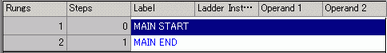
Select the first rung (MAIN START).
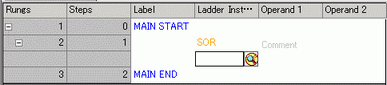
Click the icon ![]() . An SOR (Circuit Starting Point) is inserted into the rung next to the MAIN START, and then a box for adding an instruction is displayed.
. An SOR (Circuit Starting Point) is inserted into the rung next to the MAIN START, and then a box for adding an instruction is displayed.
![]()
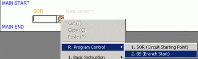
An SOR (Circuit Starting Point) can also be inserted using the ![]() icon or right-click menu as shown below.
icon or right-click menu as shown below.
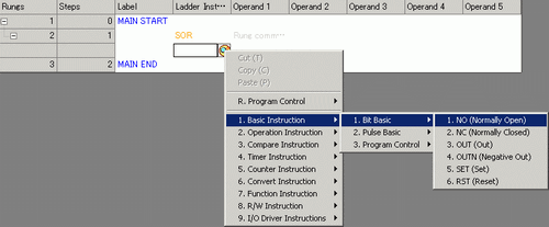
You can insert the instruction using the icon ![]() or typing the instruction name.
or typing the instruction name.
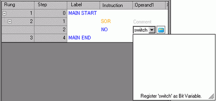
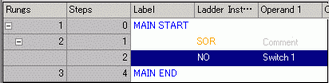
Allocate a symbol variable to [Operand 1] for the instruction.
Inserting Branches
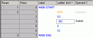
Select the instruction (NO instruction) to insert the branch.
Click the icon ![]() . BS, B and BE are inserted.
. BS, B and BE are inserted.
The sections from BS to B and from B to BE are the upper portion and lower portion of the branch, respectively, in the ladder configuration.
![]()
A BS (Branch Starting Point) can also be inserted using the ![]() icon or right-click menu as shown below.
icon or right-click menu as shown below.