30.8.1.2 Registering as a Function Block

To register a part of the existing logic program as a Function Block (FB), do the following:

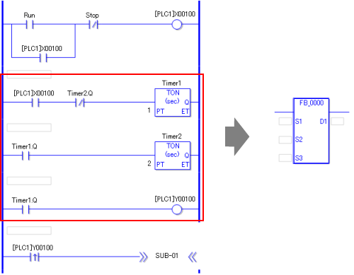
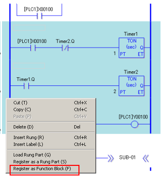
  1. In the Logic Screen, select the row which you want to register as an FB, right-click it, and select [Register as Function Block] from the pop-up menu.

    • To select multiple rows, select the first row, then click on the last row while pressing down the Shift key.

    • You can register up to 40 rows per FB, including branches.

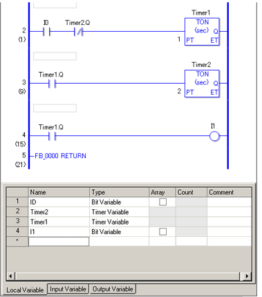
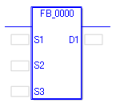
  2. The FB is registered in the Screen List window, and the editing screen opens.

    • All addresses, symbols and variables in the selected row(s) are converted to local variables. For the local variables converted from addresses, their names are converted to "I + number". (Example: I0) For those converted from symbols and variables, their original names are maintained.

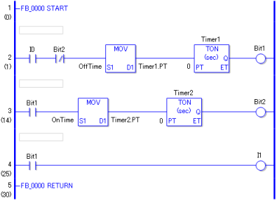
  3. In the variable list, assign local variables to [Input Variable] and [Output Variable].

Setup Procedure

The following explains how to create an FB which outputs flicker signals.

Register a program to an FB, which turns OFF Y100 for one second and ON for two seconds repeatedly while a specific bit (X100) is ON. The created FB receives the Start bit (X100) and durations of ON and OFF for the flicker signal in seconds as inputs, and outputs the flicker signal (Y100).

  1. Open the Logic Screen and select the program you want to register with the FB.

  2. Right-click, and click [Register as Function Block] from the pop-up menu.

  3. The FB is added to the [Screen List]. Double-click the FB you just added to open the editing screen.

    • All addresses and variables used in logic programs are registered as local variables.

  4. Open the variable list's [Local Variable] tab. Select a variable which receives a value as an input operand, right-click it, and click [Change to Input Variable] from the pop-up menu. (Example: change I0 to an input variable)

  5. In the [Local Variable] tab, select a variable which outputs a value as an output operand, right-click it, and click [Change to Output Variable] from the pop-up menu. (Example: change I1 to an output variable)

  6. Create two local variables. (Example: create bit variables named "Bit1" and "Bit2".)

  7. Open the variable list's [Input Variable] tab, and create two variables in order to receive the ON and OFF durations. (Example: create two integer variables named "OffTime" and "OnTime".)

    • You cannot specify array elements (X[0]) and structure elements (Timer.PT) for input and output variables.

    • You can change the order of input variables by pressing [Move up] and [Move down] buttons. By changing the order, you can change their display order as operands. (For example: If I0 order is moved down by one, S1 operand value will be changed to an integer value "OffTime" from the bit value "I0".)

  8. Modify the logic program for the Function Block as follows:

    Replace Timer1.Q with Bit1
    Replace Timer2.Q with Bit2
    Add MOV instructions to the second and third rows
    Add OUT instructions to the second and third rows
    Change the TON instructions' setting value to 0 (as a value is set for PT in MOV instruction, the behavior does not change even if you keep a constant value of 1 or 2 as the setting)

  9. You have finished creating the FB. Now, you can inset the FB in a logic program and set addresses/variables/constants for operands.

    S1: Flicker Start bit

    S2: Duration of OFF in seconds

    S3: Duration of ON in seconds

    D1: Output bit