![]()
-
Please refer to the Settings Guide for details.
 13.8 Lamp Settings Guide
 -
For details on how to draw parts, and defining the address, shape, color, and labels, please see the parts editing topic.
8.7.1 Editing Parts
![]()
Please refer to the Settings Guide for details.
![]() 13.8 Lamp Settings Guide
13.8 Lamp Settings Guide
For details on how to draw parts, and defining the address, shape, color, and labels, please see the parts editing topic.
![]() 8.7.1 Editing Parts
8.7.1 Editing Parts
The following procedure shows how to display the direction in which a crane is moved (right, left, or stop) and the error notification bit state in different colors using a single lamp. Using the following method, you can display a total of 5 states, including all bits OFF.
From the [Parts (P)] menu, point to [Switch Lamp (C)] and select [Lamp (L)] or click ![]() to place a lamp on the screen.
to place a lamp on the screen.
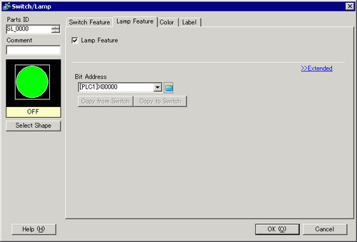
Double-click the placed lamp. The Switch/Lamp dialog box appears. Click [Extended].
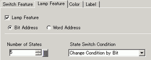
Set the [Number of States] and [State Switch Condition]. Setting the [Number of States] to 3 or more allows you to set [State Switch Condition]. (For example, [Number of States] = 5, [State Switch Condition] = Change state by bit)
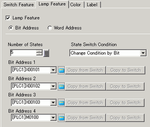
Set [Bit Address 1]. From [Input Address] dialog box select the device/PLC and set X101 to the device address, and click [Ent]. (For example, X101).
Also, set [Bit Address 2] to [Bit Address 4] as follows.
(For example [Bit Address 2] X102, [Bit Address 3] X103, [Bit Address 4] M100)
![]()
You can define each [State] by setting its corresponding bit address to either ON (1) or OFF (0).
|
State |
Description |
|||
|---|---|---|---|---|
|
Bit Address 4 |
Bit Address 3 |
Bit Address 2 |
Bit Address 1 |
|
|
[State 0] |
0 |
0 |
0 |
0 |
|
[State 1] |
0 |
0 |
0 |
1 |
|
[State 2] |
0 |
0 |
1 |
0 |
|
[State 3] |
0 |
1 |
0 |
0 |
|
[State 4] |
1 |
0 |
0 |
0 |
When multiple bits turn ON at the same time, the lamp displays in ascending order [Bit 1]->[Bit 2]->[Bit 3]->[Bit 4].
In [Select Shape], select the lamp shape for each [State].
Click the [Color] tab. In the [Select State] list, select [State 0] and define its [Display Color].
[State 0] is the state where all the specified bit addresses are OFF.
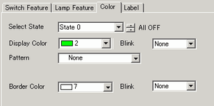
Select [State 1] in [Select State] and set the [Display Color]. [State 1] is the state where the specified Bit Address X101 is ON.
Set [Display Color] for [State 2] to [State 4].
![]()
Depending on the shape, the color setup procedure may differ from the procedure described above. Click [Select Shape]. The [Select State] window appears. Select each state and click [Open] to select a shape and color.
Depending on the shape, you may not be able to change the color.
Click the [Label] tab. Define the label to appear on the Lamp. Specify the font type and size, and then in the rectangular field type the text to display. Click [OK].
![]()
When you select a lamp and press the [F2] key, you can directly edit the text on the label.