![]()
-
Please refer to the Settings Guide for details.
 14.11.1 Numeric Display
 -
For details on how to draw parts, and defining the address, shape, and color, refer to the following.
8.7.1 Editing Parts
![]()
Please refer to the Settings Guide for details.
![]() 14.11.1 Numeric Display
14.11.1 Numeric Display
For details on how to draw parts, and defining the address, shape, and color, refer to the following.
![]() 8.7.1 Editing Parts
8.7.1 Editing Parts
From the [Parts (P)] menu, point to [Data Display (D)] and select [Numeric Display (N)], or click the ![]() icon, and place it on the screen.
icon, and place it on the screen.
Double-click the placed Data Display. The Data Display dialog box appears.
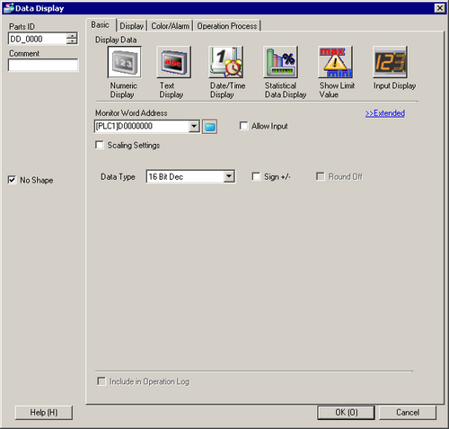
Select a part shape as necessary. Deselect [No Shape], and select a shape from [Select Shape].
In [Monitor Word Address], set up the address to store the displayed numeric value.
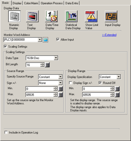
In the [Data Type] drop-down list, select the type of data to display (for example, "16 Bit Dec").
Select the [Allow Input] check box. The [Data Entry] tab is displayed.
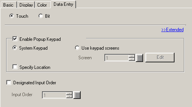
Click the [Data Entry] tab and select the [Enable Popup Keypad] check box.
On the [Data Entry] tab, click [Extended]. The following dialog box appears.
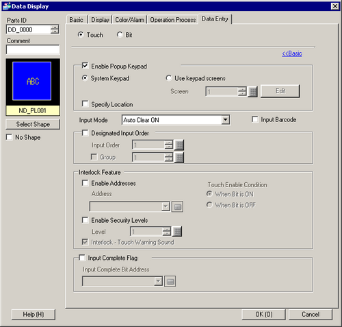
From the [Interlock Feature] area, select the [Enable Address] check box and in the [Address] field specify the bit address (M100) that will enable touch inputs.
Use the [Touch Enable Condition] options to set up a condition that enables touch inputs. (For example, select "Enable When Bit is Off" to enable touch operations when the bit is off.)
Set the font and/or color in the [Color/Alarm] and [Display] tabs as necessary and click [OK].