![]()
-
Please refer to the Settings Guide for details.
 7.9.1 System Settings [Device/PLC] Settings Guide
![]()
Please refer to the Settings Guide for details.
![]() 7.9.1 System Settings [Device/PLC] Settings Guide
7.9.1 System Settings [Device/PLC] Settings Guide
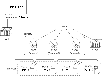
System Structure Example
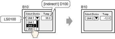
Operation Example
In the Data Display, specify the address (D100) in the indirect device (Indirect1).
Change the device/PLC using a Selector List.
Setup Procedure
Set up device/PLCs for the system. See the following system structure for the setup. For the setup procedure, see the following.
![]() 7.2.1 Procedure - Connecting to Multiple Devices/PLCs
7.2.1 Procedure - Connecting to Multiple Devices/PLCs
|
|
Device Name |
Port |
Driver |
Individual Device Settings |
|
Device/PLC1 |
PLC1 |
COM1 |
Mitsubishi Electric Corporation, Q/QnA serial communication |
|
|
Device/PLC2 |
PLC2 PLC3 PLC4 PLC5 |
COM2 |
Omron, Temp. Controller CompoWay/F |
Series=E5A/E/C/GN,UnitNo.=1 |
|
Series=E5A/E/C/GN,UnitNo.=2 |
||||
|
Series=E5A/E/C/GN,UnitNo.=3 |
||||
|
Series=E5ZN,UnitNo.=4 |
||||
|
Device/PLC3 |
PLC6 PLC7 PLC8 |
Ethernet (TCP) |
Cognex Corporation In-Sight 5000 Vision Systems |
IP address=192.168.000.001,Telnet port=23,Data Channel Port=50000,User Name=admin,Password=*****,Image Offset X=0,Image Offset Y=0,Zoom=1:1,Resolution=None |
|
IP address=192.168.000.002,Telnet port=23,Data Channel Port=50000,User Name=admin,Password=*****,Image Offset X=0,Image Offset Y=0,Zoom=1:1,Resolution=None |
||||
|
IP address=192.168.000.003,Telnet port=23,Data Channel Port=50000,User Name=admin,Password=*****,Image Offset X=0,Image Offset Y=0,Zoom=1:1,Resolution=None |
||||
|
Device/PLC4 |
PLC9 |
Ethernet (UDP) |
Mitsubishi Electric Corporation, Q/QnA Series Ethernet |
|
Set up the indirect device/PLC. In the [System Settings], click [Device/PLC] and open the [Device/PLC 2] tab.
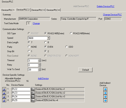
In the [Device-Specific Settings] area, on the right-side of the [PLC 2] settings, click the ![]() Add Indirect Device icon.
Add Indirect Device icon.
The indirect device appears and the Device ID fields are added to [PLC2], [PLC3] and [PLC4].

![]()
You can change the [Indirect Device Name] and Device ID. Do not use the same [Device ID] on the same driver.
Set "LS0100" in the [Device ID Address] field.
In the [Initial ID] field, define the [Device ID] device/PLC to communicate with when the [Device ID Address] is set to "0" (for example, right after the display unit is turned ON). (Example: 1)
Open the [Device/PLC 3] tab. In the [Device-Specific Settings] area, on the right-side of the [PLC 6] settings, click the ![]() Add Indirect Device icon.
Add Indirect Device icon.
The indirect device line appears and the [Device ID] fields are added to [PLC6], [PLC7] and [PLC8].

Set "LS0101" in the [Device ID Address] field.
Set the [Initial ID]. (Example: 1)
[Indirect1] and [Indirect2] are set as indirect devices. Click [Indirect Device Configuration] and check the structure.

Set up indirect devices in parts. (This example explains how to set the Indirect1.)
Open base screen 10 and draw a Data Display.
Double-click the Data Display to open its dialog box
In the [Monitor Word Address] field, click the ![]() icon to display the [Input Address] dialog box. From the [Device/PLC] list select the indirect device "Indirect1". For the device address set "C00000". Click [Ent].
icon to display the [Input Address] dialog box. From the [Device/PLC] list select the indirect device "Indirect1". For the device address set "C00000". Click [Ent].
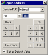
As required, define other settings such as the Data Type and Input Range and click [OK].
Next, configure settings to change the device.
On base screen 10 draw a Selector List.
Double-click the Selector List to open its dialog box
Set the [Display Count] to 3.
Select [Word Operation] and set "LS0100" in the [Word Address] field.
In the [Word Action] drop-down list, select [Write Data]. Set the [Constant] to 1. In the [Item Name Setting] field, type "Unit 1".
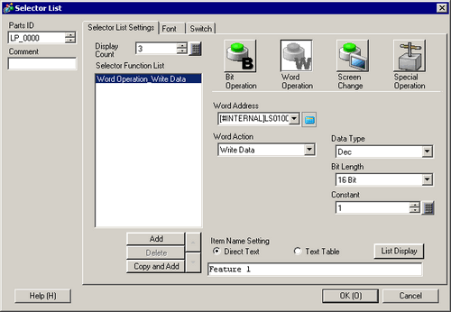
In the [Selector Function List] click [Add] and select [Word Operation].
Set the [Constant] to 2 and in the [Item Name Setting] field type "Unit 2".
In the [Selector Function List] click [Add] and select [Word Operation].
Set the [Constant] to 3 and in the [Item Name Setting] field type "Unit 3".
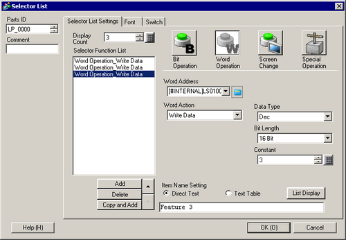
As required, define other settings such as the Font or Switch settings and click [OK].
![]()
The specified [Device ID Address] is monitored at the end of the display scan. If the value has changed, communication with the identified device/PLC starts from the next display scan.
Changing the device/PLC works the same way as screen change operations. Except for Global D-Script. Changing the device/PLC causes Global D-Script to run from the beginning (first registered script ID).
To change device and screen at the same time, use one of the following.
Use D-script to store the device ID in the [Device ID Address] and store the screen number in the system variable #H_ChangeScreenNo.
Use a multi-function switch. Add a word switch to write the device ID to the [Device ID Address], and add a change screen switch.