![]() The Special Relay is not write-protected. Do not turn it ON/OFF with Parts or write Words.
The Special Relay is not write-protected. Do not turn it ON/OFF with Parts or write Words.
![]() The Special Relay is not write-protected. Do not turn it ON/OFF with Parts or write Words.
The Special Relay is not write-protected. Do not turn it ON/OFF with Parts or write Words.
Special Relay Structure
Direct Access Method
Address |
Description |
H System Variable |
|---|---|---|
LS2032 |
Common Relay Information |
- |
LS2033 |
Base Screen Information |
- |
LS2034 |
Reserved |
- |
LS2035 |
1-Second Binary Counter |
- |
LS2036 |
Display scan time |
#H_DispScanTime |
LS2037 |
Communication Cycle Time |
- |
LS2038 |
Display scan counter |
#H_DispScanCounter |
LS2039 |
Communication Error Code |
- |
LS2040 |
Token Revolution Speed Max. Value |
#H_MAXTokenSpeed |
LS2041 |
Token Revolution Speed Current Value |
#H_CurrentTokenSpeed |
LS2042 |
Reserved |
- |
LS2043 |
||
LS2044 |
||
LS2045 |
||
LS2046 |
||
LS2047 |
Details About Each Address - Special Relay
![]()
Common Relay Information (LS2032)
0 bit
Toggles ON/OFF every communication cycle.
1 bit
After a Base screen or Window changes, turns ON until communication with all the device addresses set in the screen has succeeded and the Part operation or process has completed.
![]()
While the bit is ON, when device address communication scanning stops this bit does not turn OFF automatically.
2 bit
Turns ON only when a communication error occurs.
3 bit
Turns ON while the initial screen displays at power ON.
4 bit
Normally ON.
5 bit
Normally OFF.
6 bit
Turns ON when backup memory (SRAM) data is erased. Only onboard backup memory (SRAM)
7 bit
When using D-Scripts, turns ON when a BCD error occurs.
8 bit
When using D-Scripts, turns ON when a zero error occurs.
9 bit
Turns ON when a recipe could not be transferred to backup memory (SRAM).
10 bit
Turns ON when filing data transfer initiated by the Control Word Address could not transfer from PLC to SRAM. Also, when transferring from a PLC by way of a Special Data Display (filing), and when using the Transfer Complete Bit Address, it turns ON when data could not transfer between PLC -> Internal Device, or PLC -> SRAM.
11 bit
Turns ON during transfer between SRAM <-> Internal Device by means of a Special Data Display (Filing).
12 bit
When using D-Scripts, turns ON when a communication error occurs from a memcpy ( ) or address offset designation read. Turns OFF when data finishes reading normally.
13 bit
In the [System Settings] [Script I/O] page, when no [D-Script/Global D-Script] is set in the project, turns ON when the readout of the Send function, Receive function, Control, Status variable, and Received Data Size is executed in [SIO Port Operation]'s Label Settings.
14 bit
In the [System Settings] [Script I/O] page, when [D-Script/Global D-Script] is set in the project, turns ON when an extended script's [Text Operation] function is executed. Also, in the [System Settings] [Script I/O] page, when [Extended Script] is set in the project, turns ON even when a D-Script/Global D-Script [SIO Port Operation]'s I/O function (IO_WRITE, IO_READ) is executed.
15 bit
Reserved
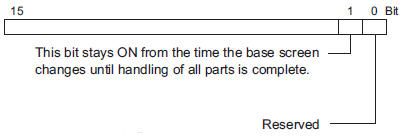
Base Screen Information (LS2033)

![]()
While bit 1 is ON, when communication scanning stops for device addresses set up on the display, bit 1does not turn OFF automatically.
Reserved (LS2034, LS2040 to LS2047)
Values are undefined in reserved addresses. Do not use.
1-Second Binary Counter (LS2035)
Increments once every second immediately after the power is turned ON. Data is in Bin format.
The display time starts from the first Part set on the display screen to the end of the last Part. Data is stored in Bin format, in millisecond units. The data is updated when all processing for the target Parts has finished. The data's initial value is "0".
There is an error of +/-10 ms.
The time it takes from the start to the end of scanning the addresses (PLC or other) mapped to the System Data Area. Data is stored in Bin format, in 10 millisecond units. The data is updated when all processing for the System Data Area and target device has finished. The data's initial value is "0".
There is an error of +/-10 ms.
![]()
When multiple devices/PLCs are connected to a single display unit, the System Data Area can only be allotted to one device/PLC.
Display Scan Counter (LS2038)
The counter increments each time the Part set on the display screen processes. Data is in Bin format.
When a communication error occurs, the last displayed communication error code is stored in Bin format.
Maximum Token Revolution Speed (LS2040)
Used only during a Serial Multilink connection.
The maximum value of the time it takes for one transfer cycle of a token packet (a Command Right for PLC) through multiple connected Displays. The unit is 10 milliseconds. The data is updated every time the maximum value is changed or when the screen is changed. The data's initial value is "0". There is an error of +/-10 ms.
Current Token Revolution Speed (LS2041)
Used only during a Serial Multilink connection.
The current value of the time it takes for one transfer cycle of a token packet (a Command Right for PLC) through multiple connected Displays. The unit is 10 milliseconds. The data is updated every time the maximum value is changed or when the screen is changed. The data's initial value is "0". There is an error of +/-10 ms.